A Bms Wire Harness is the physical link between battery cells, sensors, and the battery management system. It carries voltage signals, temperature readings, balancing currents, and communication data. In an electric vehicle, the harness may run through narrow channels beside cell modules. Small connectors must remain secure despite vibration, heat, moisture, and repeated charging cycles.
The International Energy Agency’s Global EV Outlook 2024 reported almost 14 million electric cars sold worldwide in 2023. Electric vehicles represented about 18% of global car sales. This growth increases demand for dependable battery wiring and accurate monitoring. A correctly designed Bms Wire Harness helps the control unit detect abnormal voltage, rising temperatures, or damaged connections. It can support safer charging and earlier fault isolation. Every terminal matters.
Industry practice also reflects automotive safety standards such as ISO 26262, while connector selection may consider requirements from USCAR and LV 214 testing methods. These references emphasize electrical integrity, mechanical durability, insulation performance, and traceable validation. The harness should be checked for correct pin mapping, resistance, shielding, bend radius, and connector locking force. A loose terminal can create heat. That risk is easy to underestimate.
Yet, the harness is not merely a bundle of colored wires. Its routing affects serviceability, electromagnetic performance, and thermal exposure. Manufacturers often improve designs after field inspections, because laboratory conditions cannot reproduce every vehicle vibration pattern. This is where practical engineering experience matters. A perfect drawing can still fail in production. Careful crimp inspection, end-of-line testing, and documented quality controls make the Bms Wire Harness a reliable part of the battery system, not an afterthought.
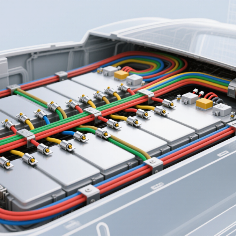
A BMS wire harness is an organized group of insulated wires, terminals, and protective sleeves. It connects a battery management system with battery cells, sensors, contactors, and charging circuits. Think of it as the battery’s communication and measurement pathway. Each wire carries a defined signal or current.
Its core purpose is accurate monitoring and controlled power flow. Thin sensing wires measure individual cell voltages, while temperature leads report conditions near cells or busbars. Heavier conductors may carry power to the control unit or switching devices. The harness also keeps connections arranged, labeled, and protected from vibration. Without this structure, testing and maintenance become slower and more error-prone.
A reliable harness needs correct wire length, terminal crimping, insulation, and connector locking. Poor contact pressure can create resistance, heat, or unstable readings. That detail is easy to overlook. Engineers normally check continuity, polarity, insulation, and mechanical strain before installation. Routing also matters; sharp edges and excessive bending can damage insulation over time. In practical battery assembly, a harness may look simple, but its pin arrangement is highly specific. One misplaced connection can distort cell data or interrupt protection functions. Even experienced technicians should verify the wiring diagram rather than rely on memory. Definitions sometimes differ between projects, so clear documentation remains essential.
What Is a BMS Wire Harness and How Does It Work?
A BMS wire harness connects battery cells to the monitoring system. Its main job is accurate, stable signal transmission. Thin sense wires measure voltage at each cell or cell group. A low-voltage connector carries these signals to the control board. One loose terminal can create a false reading.
Temperature sensor wires track heat near cells, busbars, or connection points. These sensors help the BMS detect unusual temperature changes. Current-sensing wires connect with a shunt or magnetic sensor. They report charging and discharging current. The BMS uses this data to estimate battery condition and control protection functions. Balance wires support controlled energy release from higher-voltage cells. This helps reduce voltage differences across the pack.
Physical design matters as much as electrical design. Wires need secure routing, suitable insulation, and strain relief. Abrasion near a metal enclosure remains a common failure risk. Shielding may reduce electrical noise in demanding installations. However, shielding alone cannot repair poor grounding or weak terminals. A careful inspection checks connector locks, crimp quality, wire labels, and bend radius. Small details matter.
The harness is not a decorative bundle. It is the BMS’s measurement pathway. If resistance changes with vibration, readings may drift. That possibility is sometimes overlooked. Good designs also allow service access without pulling directly on sensor wires. In real projects, documentation can be imperfect, so clear labeling and measured verification remain essential.
| Harness Component | Primary Role | What It Monitors or Controls | Typical Connection Points | Key Design Considerations |
|---|---|---|---|---|
| Cell Voltage Tap Wires | Carry individual cell or cell-group voltage signals to the battery-monitoring electronics. | Cell voltage, voltage imbalance, overvoltage, and undervoltage conditions. | Cell terminals, busbars, module monitoring boards, or a centralized BMS measurement connector. | Correct wire sequence, insulation, creepage distance, strain relief, and protection against accidental short circuits are essential. |
| Temperature Sensor Wires | Connect temperature sensors to the BMS for thermal condition monitoring. | Cell, module, busbar, connector, or enclosure temperature. | Negative-temperature-coefficient thermistors or other approved temperature sensors and BMS input channels. | Sensor placement should represent the hottest areas; wires should be routed away from high-current conductors where practical. |
| Current Sensor Wiring | Transmit battery-current measurements to the BMS. | Charge current, discharge current, current direction, and accumulated charge flow. | Shunt, Hall-effect sensor, or other isolated current-measurement device. | Signal polarity, sensor isolation, low-noise routing, and secure low-voltage connectors help maintain measurement accuracy. |
| Contactor Control Wires | Allow the BMS to open or close high-voltage switching devices. | Battery connection status, pre-charge operation, charge enable, and discharge enable. | Positive contactor, negative contactor, pre-charge contactor, and their driver circuits. | The harness must support the specified coil voltage and current while maintaining separation from high-voltage power paths. |
| Pre-Charge Circuit Wires | Support controlled charging of the external DC-link capacitors before the main contactors close. | Pre-charge timing, voltage rise, and abnormal inrush-current conditions. | Pre-charge contactor, resistor, voltage measurement points, and BMS control circuitry. | Incorrect sequencing can cause excessive inrush current or prevent the battery from connecting safely. |
| High-Voltage Interlock Loop Wires | Provide a continuity-check circuit for high-voltage covers, connectors, and service-access points. | Open connectors, removed covers, or compromised enclosure access points. | Interlock switches, high-voltage connectors, service disconnects, and BMS or vehicle control inputs. | A detected open circuit should trigger a defined protective response, such as opening the contactors. |
| Low-Voltage Power Wires | Supply operating power and reference connections to BMS electronics and sensors. | BMS operating status, sensor reference levels, and internal diagnostic conditions. | Auxiliary battery, regulated power supply, BMS controller, monitoring boards, and sensor circuits. | Fuse protection, correct polarity, voltage-drop control, and reliable grounding are required. |
| Communication Wires | Exchange measurements, warnings, limits, and control commands between BMS modules and external controllers. | State of charge, state of health, temperature data, fault codes, charge limits, and contactor requests. | BMS controller, monitoring units, charger, inverter, vehicle controller, or energy-management system. | Bus termination, twisted-pair routing where applicable, shielding, signal integrity, and communication protocol compatibility matter. |
| Shielding and Reference Conductors | Reduce electromagnetic interference and provide controlled signal reference paths. | Stable low-level voltage, current, temperature, and communication signals. | Cable shields, signal grounds, chassis reference points, and BMS connector terminals. | Shield termination and grounding should follow the system's electrical and electromagnetic-compatibility design. |
| Connectors and Terminals | Create detachable electrical and mechanical interfaces between the harness, cells, sensors, modules, and control electronics. | All signals and power paths carried by the harness. | Cell tabs or busbars, sensor leads, BMS boards, contactors, current sensors, and external system interfaces. | Keying, locking, touch protection, sealing, terminal retention, corrosion resistance, and serviceability are important. |
| Protective Sleeving and Routing Features | Protect conductors from abrasion, heat, vibration, moisture, and incorrect movement. | Harness integrity and long-term signal reliability. | Braided sleeving, conduit, clips, grommets, strain reliefs, labels, and fastening points. | Routing should avoid sharp edges, hot surfaces, moving parts, and unnecessary proximity to high-current or high-noise conductors. |
A BMS wire harness combines measurement, control, communication, power, and safety circuits so the battery-management system can evaluate battery condition and respond to abnormal electrical or thermal conditions.
A BMS wire harness connects battery cells, sensors, control boards, and protection devices. It carries power and data through carefully arranged wires. Thick conductors handle current between the battery pack and external equipment. Smaller wires measure individual cell voltages and temperatures. Each signal follows a defined path through connectors and terminal points.
Cell-voltage wires report small differences between neighboring cells. Temperature wires send resistance changes from sensors placed near hot spots. The BMS compares these readings and detects imbalance, overheating, or unusual voltage behavior. Communication lines may use twisted pairs to reduce electrical noise. Shielding can help in electrically demanding environments. However, shielding alone cannot repair poor grounding or loose terminals.
Power paths usually include fuses, contactors, and isolation features. These parts help control high current during charging, discharging, and fault conditions. Data signals travel separately from heavy-current conductors whenever the layout allows. This reduces interference and simplifies troubleshooting. During inspection, technicians should verify pin assignments, crimp quality, wire labels, and connector locking. A harness may look neat but still contain a reversed sensor lead. That detail is easy to miss. Measuring continuity is useful, yet it does not prove correct polarity or insulation performance. Practical validation should include voltage checks, temperature simulation, and movement testing under realistic conditions.
A BMS wire harness is the electrical pathway between battery cells, sensors, and the control unit. It carries cell-voltage signals, temperature readings, and sometimes current information. In practice, technicians route the harness along protected channels inside the battery pack. Each connector must seat firmly, while every wire needs the correct position. Small errors matter. A loose terminal can create unstable readings or local heating. The harness may also include shielding, insulation, and physical supports that reduce vibration and abrasion.
During charging or discharging, the BMS receives continuous data through these wires. It compares individual cell voltages and checks temperatures at several points. When a cell reaches an unsafe limit, the control system can reduce current or command contactors to open. This protects the pack from overcharging, excessive discharge, and thermal stress. The harness itself does not make the safety decision. It provides the reliable signal path that allows the BMS to respond quickly. Damaged insulation, moisture, or excessive resistance can distort that information.
A careful inspection checks connector locks, pin alignment, bend radius, and signs of rubbing. Measurements should also confirm continuity and insulation quality before the pack enters service. Vibration testing is useful because a harness can pass a bench test yet fail after repeated movement. This is an imperfect area. Even a well-designed harness may develop a hidden intermittent fault. Engineers should allow inspection access and avoid routing wires near sharp edges or hot surfaces. Clear labeling helps technicians trace each circuit without guesswork.
A BMS wire harness links battery cells, voltage sensors, temperature probes, contactors, and the control unit. Its design affects safety, measurement accuracy, and service life. The International Energy Agency reported nearly 14 million electric cars sold globally in 2023. That scale makes harness reliability a production issue, not a minor wiring detail.
Engineers should separate high-voltage conductors from low-level sensing wires. Twisted signal pairs can reduce electromagnetic interference. Locking connectors, abrasion sleeves, and strain reliefs protect joints near vibrating battery modules. Design reviews should check bend radius, creepage distance, thermal exposure, and assembly access. A small routing mistake can create a large diagnostic problem.
Testing needs more than continuity checks. Teams should measure insulation resistance, withstand voltage, terminal retention, crimp height, and sensor resistance. The IPC/WHMA-A-620 standard provides widely used acceptance guidance for cable and harness workmanship. The U.S. Department of Energy’s Vehicle Technologies Office has repeatedly identified thermal management and battery durability as key development priorities. Harness tests should therefore include heat cycling, humidity, vibration, and coolant contamination.
Maintenance records should track intermittent faults, not only complete failures. Inspect darkened terminals, loosened seals, exposed shielding, and crushed insulation. Use calibrated meters and follow the battery maker’s service procedure. In practice, technicians sometimes replace an entire harness too quickly. That is convenient, but it can hide a poor crimp or damaged connector. A better repair decision requires evidence, photographs, and repeat testing. Mistakes still happen. Clear labeling helps prevent them.